Basic Elements of a Pneumatic System


A – Compressor: a pump which compresses air, raising it to a higher pressure, and delivers it to the pneumatic system (sometimes, can also be used to generate a vacuum).

B – Check valve: one-way valve that allows pressurized air to enter the pneumatic system, but prevents backflow (and loss of pressure) into the compressor when it is stopped.

C – Accumulator: stores compressed air, preventing surges in pressure and relieving the duty cycle of the compressor.

D – Directional valve: controls the flow of pressurized air from the source to the selected port. Some valves permit free exhaust from the port not selected. These valves can be actuated either manually or electrically (the valves typically provided in the FIRST kits use dual solenoids to change the direction of the valve, based on input signals from the control system).

E – Actuator: converts energy stored in the compressed air into mechanical motion. A linear piston is shown. Alternate tools include rotary actuators, air tools, expanding bladders, etc.

What is Mechatronics?

Back in the early 1970s, Japanese industry coined the word Mechatronics in relation to the development of the world's first industrial robots. Robotics has since come to be regarded as a generic term, and yet it forms only a subset of Mechatronics, which still lacks recognition in some quarters as an indigenous term in our technological vocabulary. 'Mechatronics ' is a natural choice for explaining a process that seeks, from the outset, to generate definitive engineering system solutions, which are inextricably bound by those integrating technologies associated with the inveterate mechanical, electronic and computer based disciplines.

First and foremost Mechatronics should be seen to represent technology integration and not merely a combination of the primary disciplines. In fact, the 'fusion' of mechanical, electronic and computer based structures into a complete Mechatronics 'product' can only achieve its desired functionality through a process of systematic integration of all inherent disciplines involved right through from the conceptual stages. Invoking only mechanical electronic or computer-based entities would not in itself provide the complete system solution. In reality, Mechatronics opens up enormous technological possibilities, as already evidenced by the appearance of sophisticated products like ever-smaller camcorders and compact disc players. These would never have been plausible by adopting a traditional single disciplinary or combinational approach. By definition, then, Mechatronics is not a subject, science or technology per se - it is instead to be regarded as a philosophy - a fundamental way of looking at and doing things, and by its very nature requires a unified approach to its delivery.

The traditional western approach has relied on single discipline identities and evolutionary solutions based on bolt-on technology. On the other hand, Mechatronics solutions require the use of integrated teams of personnel working towards a common goal. Thus the Mechatronics engineer identifies with systems thinking, and a philosophy that lies behind it all. A Mechatronics 'product' derived through systematic, rather than piecemeal processing. It, therefore, seeks to optimize an 'engineered' solution rather than compromise it. Mechatronics philosophy adequately describes the process by which it is achieved. This insight quite naturally lends itself to the concept of 'total quality', something that western industrialized nations have only in the last decade or so come to aspire to. But for Mechatronics, quality is already implied by the way in which system based solutions are to be sought, and the methodologies used for achieving it. It is hoped that industry and commerce will similarly come to respect and aspire to Mechatronics for what it stands for - total synergy.

What do Mechatronics Engineers do?

Mechatronics combines mechanical, electrical and software engineering in the design, development and control of diverse systems used in a range of industries including manufacturing, medicine and the service industries. Examples of mechatronic systems include aircraft, dishwashers, motor vehicles, automated manufacturing plants, medical and surgical devices and systems, robots of all types, many toys, artificial organs and many others. Mechatronics engineers are therefore involved in almost every possible industry at levels from applications development to manufacturing to advanced research.

Where do Mechatronics Engineers work?

Graduates with a Mechatronics degree can take up careers in a wide spectrum of industries including robotics, aerospace, chemical, defence and automotive and manufacturing where complex software plays a major role, as well as in businesses that require extensive computer support, such as banking and commerce. Contributions can be made to these industries in a variety of roles including design engineer, software engineer, project planner, product designer and project manager.

Some Common Pneumatic Circuits

Controlling Cylinder Speed


Five Ported Four Way

Description:

4-Way

4 Flow Directions

2 - Position

Actuated/at rest

Normally Passing Classification

Not Applicable

Push Button, Spring Return

Operator Type

5 Ports

1, 2, 3, 4, and 5

Each cylinder port has its own exhaust

Standard labels apply --- ISO standard shown above, may also be:


Sandwich Speed Control


NOTE:

  • Dotted line indicates an assembly --- a modular combination of devices; in this case a valve and a speed control sandwich.
  • Metering devices are needle valves and serve to restrict only the exhaust --- supply is full flow.
  • Modular design allows control from the valve (often the cylinder is inaccessible or in a protected cell).
  • Only by restricting both exhaust flow paths can we extend and retract at the same speed.

Controlling Cylinder Force

NOTE:

  • Dotted line indicates an assembly---a modular combination of devices; in this case a valve and a double regulator sandwich.
  • Observe that the addition of the sandwich regulator has altered the valve flow paths. IMPORTANT!
  • Modular design allows control from the valve's location.
  • A direct acting multi-purpose valve can have supply and even different pressures at ports other than 1 or P---achieving different functions.

Vacuum Cap

Objective: Vacuum cup picks up part/part blow off

NOTE:

  • Valve in "12" condition has vacuum at the cup and regulated air fills a small volume chamber.
  • Valve in "14" condition has vacuum blocked and a puff of air breaks the vacuum lock and blows off the part. Force is adjustable. Volume chamber sized for volume required by the circuit.
  • Valve selected to maintain position in the event of power failure --- double solenoid detent also only requires momentary pulse of electricity.
  • Single valve solution/saves energy/fail safe/adjustable.

Cylinder Deceleration

Objective: Cylinder Decel Circuit or Varying Clamp Force

NOTE:

  • Cylinder extends and retracts with signal to main valve.
  • Pressure to main valve controlled by selector valve.
  • Cylinder can extend, then, with higher pressure selected, clamp with greater force.
  • Varying selected pressures can decelerate/accelerate the cylinder.


Three Position Valve

OBSERVE:

Cylinder will not stop until the back pressure rises high enough to balance the forces on the piston --- analysis follow.

NOTE:

  • Air is trapped in the cylinder. Any leakage (fittings, piston seal, rod seal, valve) will allow the cylinder to move or drift.
  • When air is exhausted by a lockout or dump valve, air will be trapped in cylinder.
  • If load is vertical --- any cylinder lines' inadvertent exhaust will cause the load to drop unexpectedly.
  • During start up --- the all ports blocked center valve does not allow the air to pressurize the cylinder. First stroke could be at high speed due to potential lack of air at either end of cylinder.
  • Disconnecting any air lines for maintenance may cause unexpected rapid movement of the cylinder --- even if OSHA lock out has been correctly actuated.
These actions may occur when least expected


Three Position Valve 2

NOTE:

  • Check valves stop and hold cylinder in mid position.
  • Regulators balance pressures.
  • In case of electrical failure, valve defaults to mid position, and the check valves stop and maintain cylinder position.
  • In case of pneumatic supply failure, valve defaults to mid position, and the check valves stop and maintain cylinder position.
  • During start up, first cycle does not cause rapid cylinder motion.
  • Be aware, however, air will be trapped even if a lock out valve is opened upstream of this valve.


Strain Gauge Configuration Types

Wheatstone Bridges and Strain Gauges

All strain-gauge configurations are based on the concept of a Wheatstone bridge. A Wheatstone bridge is a network of four resistive legs. One or more of these legs can be active sensing elements. Figure 1-1 shows a Wheatstone bridge circuit diagram.
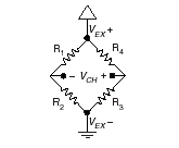
Figure 1-1. Basic Wheatstone Bridge Circuit Diagram


The Wheatstone bridge is the electrical equivalent of two parallel voltage divider circuits. R1 and R2 compose one voltage divider circuit, and R4 and R3 compose the second voltage divider circuit. The output of a Wheatstone bridge is measured between the middle nodes of the two voltage dividers.

A physical phenomena, such as a change in strain applied to a specimen or a temperature shift, changes the resistance of the sensing elements in the Wheatstone bridge. The Wheatstone bridge configuration is used to help measure the small variations in resistance that the sensing elements produce corresponding to a physical change in the specimen.

Strain-gauge configurations are arranged as Wheatstone bridges. The gauge is the collection of all of the active elements of the Wheatstone bridge. There are three types of strain-gauge configurations: quarter-bridge, half-bridge, and full-bridge. The number of active element legs in the Wheatstone bridge determines the kind of bridge configuration. Refer to Table 1-1 to see how many active elements are in each configuration.


Each of these three configurations is subdivided into multiple configuration types. The orientation of the active elements and the kind of strain measured determines the configuration type. National Instruments (NI) supports seven various configuration types in software. However, with custom software scaling all Wheatstone bridge configuration types can be used with any NI hardware product that supports your gauge configuration type.

The supported strain gauge configuration types measure axial strain, bending strain, or both. While some similar configuration types can be used to measure torsional strain, NI’s software scaling does not support these configuration types. It is possible to use NI products to measure torsional strain, but to properly scale these configuration types you must create a custom scale in Measurement & Automation Explorer (MAX) or perform scaling in your software application.

This document discusses all of the mechanical, electrical, and scaling considerations of each strain-gauge configuration type supported by NI.

Acronyms, Formulas, and Variable Definitions

In the figures and equations in this document, the acronyms, formulas, and variables are defined as:

e is the measured strain (+e is tensile strain and -e is compressive strain).

eS is the simulated strain.

GF is the Gauge Factor, which should be specified by the gauge manufacturer.

Rg is the nominal gauge resistance, which should be specified by the gauge manufacturer.

RL is the lead resistance. If lead lengths are long, RL can significantly impact measurement accuracy.

Rs is the shunt calibration resistor value.

U is the ratio of expected signal voltage to excitation voltage with the shunt calibration circuit engaged. Parameter U appears in the equations for simulated strain and is defined by the following equation:


n is the Poisson’s ratio, defined as the negative ratio of transverse strain to axial strain (longitudinal) strain.

VCH is the measured signal’s voltage.

VEX is the excitation voltage.

Vr is the voltage ratio that is used in the voltage to strain conversion equations and is defined by the following equation:


Software Scaling and Equations

Once you have acquired the voltage signal VCH , you can scale this voltage to the appropriate strain units in software. This is done automatically for you in traditional NI-DAQ using the strain virtual channel and in NI-DAQmx using a strain task or strain channel. You can also scale the voltages manually in your application using the voltage to strain conversion equations provided in this document for each configuration type.


Finally, there are voltage to strain conversion functions included in LabVIEW, traditional NI-DAQ, and NI-DAQmx. In LabVIEW, the conversion function, Convert Strain Gauge Reading.vi, is in the Data Acquisition»Signal Conditioning subpalette. The prototypes for the NI-DAQ functions, Strain_Convert and Strain_Buf_Convert, are in the header file convert.h for C/C++, and convert.bas for Visual Basic. In LabVIEW 7.x or earlier, refer to the Traditional NI-DAQ User Manual and the LabVIEW Measurements Manual for more information. In LabVIEW 8.0 or later, refer to the Traditional NI-DAQ User Manual and the Strain Gauges topic in the LabVIEW Help.

The names given the strain-gauge types in the following sections directly correspond to bridge selections in MAX and the LabVIEW Convert Strain Gauge Reading VI.

Quarter-Bridge Type I

This section provides information for the quarter-bridge strain-gauge configuration type I. The quarter-bridge type I measures either axial or bending strain.
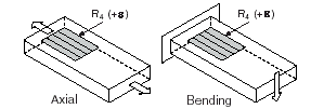
Figure 1-2. Quarter-Bridge Type I Measuring Axial and Bending Strain


A quarter-bridge type I has the following characteristics:

• A single active strain-gauge element is mounted in the principle direction of axial or bending strain.

• A passive quarter-bridge completion resistor (dummy resistor) is required in addition to half-bridge completion.

• Temperature variation in specimen decreases the accuracy of the measurements.

• Sensitivity at 1000 me is ~ 0.5 mVout/ VEX input.

Figure 1-3. Quarter-Bridge Type I Circuit Diagram


The following symbols apply to the circuit diagram and equations:

• R1 and R2 are half-bridge completion resistors.

• R3 is the quarter-bridge completion resistor (dummy resistor).

• R4 is the active strain-gauge element measuring tensile strain (+e).

To convert voltage readings to strain units use the following equation:


To simulate the effect on strain of applying a shunt resistor across R3, use the following equation:

Quarter-Bridge Type II


This section provides information for the quarter-bridge strain-gauge configuration type II. The quarter-bridge type II measures either axial or bending strain.


Figure 1-4. Quarter-Bridge Type II Measuring Axial and Bending Strain


A quarter-bridge type II has the following characteristics:

• One active strain-gauge element and one passive, temperature-sensing quarter-bridge element (dummy gauge). The active element is mounted in the direction of axial or bending strain. The dummy gauge is mounted in close thermal contact with the strain specimen but not bonded to the specimen, and is usually mounted transverse (perpendicular) to the principle axis of strain.

• This configuration is often confused with the half-bridge type I configuration, with the difference being that in the half-bridge type I configuration the R3 element is active and bonded to the strain specimen to measure the effect of Poisson’s ratio.

• Completion resistors provide half bridge completion.

• Compensates for temperature.

• Sensitivity at 1000 me is ~ 0.5 mVout/ VEX input.
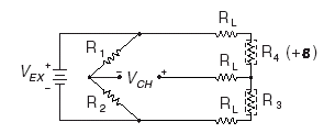
Figure 1-5. Quarter-Bridge Type II Circuit Diagram


The following symbols apply to the circuit diagram and equations:

• R1 and R2 are a half-bridge completion resistors.

• R3 is the quarter-bridge temperature-sensing element (dummy gauge).

• R4 is the active strain-gauge element measuring tensile strain (+e).

To convert voltage readings to strain units use the following equation:


To simulate the effect on strain of applying a shunt resistor across R3, use the following equation:


Half-Bridge I


This section provides information for the half-bridge strain-gauge configuration type I. The half-bridge type I measures either axial or bending strain.
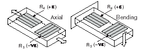
Figure 1-6. Half-bridge Type I Measuring Axial and Bending Strain


A half-bridge type I has the following characteristics:

• Two active strain-gauge elements. One is mounted in the direction of axial strain, the other acts as a Poisson gauge and is mounted transverse (perpendicular) to the principal axis of strain.

• Completion resistors provide half bridge completion.

• Sensitive to both axial and bending strain.

• Compensates for temperature

• Compensates for the aggregate effect on the principle strain measurement due to the Poisson’s ratio of the specimen material.

• Sensitivity at 1000 me is ~ 0.65 mVout/ VEX input.

Figure 1-7. Half-Bridge Type I Circuit Diagram


The following symbols apply to the circuit diagram and equations:

• R1 and R2 are half-bridge completion resistors.

• R3 is the active strain-gauge element measuring compression from Poisson effect (–ne).

• R4 is the active strain-gauge element measuring tensile strain (+e).

To convert voltage readings to strain units use the following equation:


To simulate the effect on strain of applying a shunt resistor across R3, use the following equation:

Half-Bridge II

This section provides information for the half-bridge strain-gauge configuration type II. The half-bridge type II only measures bending strain.

Figure 1-8. Half-Bridge Type II Rejecting Axial and Measuring Bending Strain


A half-bridge type II configuration has the following characteristics:

• Two active strain-gauge elements. One is mounted in the direction of bending strain on one side of the strain specimen (top), the other is mounted in the direction of bending strain on the opposite side (bottom).

• Completion resistors provide half bridge completion.

• Sensitive to bending strain.

• Rejects axial strain.

• Compensates for temperature.

• Sensitivity at 1000 me is ~ 1 mVout/ VEX input.
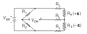

Figure 1-9. Half-Bridge Type II Circuit Diagram

The following symbols apply to the circuit diagram and equations:

• R1 and R2 are half-bridge completion resistors.

• R3 is the active strain-gauge element measuring compressive strain (–e).

• R4 is the active strain-gauge element measuring tensile strain (+e).

To convert voltage readings to strain units use the following equation:


To simulate the effect on strain of applying a shunt resistor across R3, use the following equation:


Full-Bridge I


This section provides information for the full-bridge strain-gauge configuration type I. The full-bridge type I only measures bending strain.


Figure 1-10. Full-Bridge Type I Rejecting Axial and Measuring Bending Strain

A full-bridge type I configuration has the following characteristics:

• Four active strain-gauge elements. Two are mounted in the direction of bending strain on one side of the strain specimen (top), the other two are mounted in the direction of bending strain on the opposite side (bottom).

• Highly sensitive to bending strain.

• Rejects axial strain.

• Compensates for temperature.

• Compensates for lead resistance.

• Sensitivity at 1000 me is ~ 2.0 mVout / VEX input.
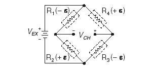

Figure 1-11. Full-Bridge Type I Circuit Diagram

The following symbols apply to the circuit diagram and equations:

• R1 is an active strain-gauge element measuring compressive strain (–e).

• R2 is an active strain-gauge element measuring tensile strain (+e).

• R3 is an active strain-gauge element measuring compressive strain (–e).

• R4 is an active strain-gauge element measuring tensile strain (+e).

To convert voltage readings to strain units use the following equation:


To simulate the effect on strain of applying a shunt resistor across R3, use the following equation:


Full-Bridge II


This section provides information for the full-bridge type II strain-gauge configuration. The full-bridge type II only measures bending strain.
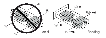

Figure 1-12. Full-Bridge Type II Rejecting Axial and Measuring Bending Strain

A full-bridge type II configuration has the following characteristics:

• Four active strain-gauge elements. Two are mounted in the direction of bending strain with one on one side of the strain specimen (top), the other on the opposite side (bottom). The other two act together as a Poisson gauge and are mounted transverse (perpendicular) to the principal axis of strain with one on one side of the strain specimen (top), the other on the opposite side (bottom).

• Rejects axial strain.

• Compensates for temperature.

• Compensates for the aggregate effect on the principle strain measurement due to the Poisson’s ratio of the specimen material.

• Compensates for lead resistance.

• Sensitivity at 1000 me is ~ 1.3 mVout / VEX input.
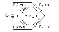

Figure 1-13. Full-Bridge Type II Circuit Diagram

The following symbols apply to the circuit diagram and equations:

• R1 is an active strain-gauge element measuring compressive Poisson effect (–ne).

• R2 is an active strain-gauge element measuring tensile Poisson effect (+ne).

• R3 is an active strain-gauge element measuring compressive strain (–e).

• R4 is an active strain-gauge element measuring tensile strain (+e).

To convert voltage readings to strain units use the following equation:


To simulate the effect on strain of applying a shunt resistor across R3, use the following equation:


Full-Bridge III


This section provides information for the full-bridge strain-gauge configuration type III. The full-bridge type III only measures axial strain.
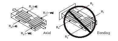
Figure 1-14. Full-Bridge Type III Measuring Axial and Rejecting Bending Strain


A full-bridge type III configuration has the following characteristics:

• Four active strain-gauge elements. Two are mounted in the direction of axial strain with one on one side of the strain specimen (top), the other on the opposite side (bottom). The other two act together as a Poisson gauge and are mounted transverse (perpendicular) to the principal axis of strain with one on one side of the strain specimen (top), the other on the opposite side (bottom).

• Compensates for temperature.

• Rejects bending strain.

• Compensates for the aggregate effect on the principle strain measurement due to the Poisson’s ratio of the specimen material.

• Compensates for lead resistance.

• Sensitivity at 1000 me is ~ 1.3 mVout / VEX input.
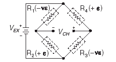
Figure 1-15. Full-Bridge Type III Circuit Diagram


The following symbols apply to the circuit diagram and equations:

• R1 is an active strain-gauge element measuring compressive Poisson effect (–ne).

• R2 is an active strain-gauge element measuring tensile strain (+e).

• R3 is an active strain-gauge element measuring compressive Poisson effect (–ne).

• R4 is an active strain-gauge element measuring the tensile strain (+e).

To convert voltage readings to strain units use the following equation:


To simulate the effect on strain of applying a shunt resistor across R3, use the following equation:


Courtesy of National Instruments

Strain and Strain Gauges

What Is Strain?

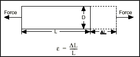
Strain is the amount of deformation of a body due to an applied force. More specifically, strain (e) is defined as the fractional change in length, as shown in Figure 1 below.


Figure 1. Definition of Strain


Strain can be positive (tensile) or negative (compressive). Although dimensionless, strain is sometimes expressed in units such as in./in. or mm/mm. In practice, the magnitude of measured strain is very small. Therefore, strain is often expressed as microstrain (me), which is e x 10-6.

When a bar is strained with a uniaxial force, as in Figure 1, a phenomenon known as Poisson Strain causes the girth of the bar, D, to contract in the transverse, or perpendicular, direction. The magnitude of this transverse contraction is a material property indicated by its Poisson's Ratio. The Poisson's Ratio n of a material is defined as the negative ratio of the strain in the transverse direction (perpendicular to the force) to the strain in the axial direction (parallel to the force), or n = eT/e. Poisson's Ratio for steel, for example, ranges from 0.25 to 0.3.

The Strain Gauge


While there are several methods of measuring strain, the most common is with a strain gauge, a device whose electrical resistance varies in proportion to the amount of strain in the device. The most widely used gauge is the bonded metallic strain gauge.

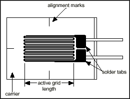
The metallic strain gauge consists of a very fine wire or, more commonly, metallic foil arranged in a grid pattern. The grid pattern maximizes the amount of metallic wire or foil subject to strain in the parallel direction (Figure 2). The cross sectional area of the grid is minimized to reduce the effect of shear strain and Poisson Strain. The grid is bonded to a thin backing, called the carrier, which is attached directly to the test specimen. Therefore, the strain experienced by the test specimen is transferred directly to the strain gauge, which responds with a linear change in electrical resistance. Strain gauges are available commercially with nominal resistance values from 30 to 3000 Ω, with 120, 350, and 1000 Ω being the most common values.


Figure 2. Bonded Metallic Strain Gauge


It is very important that the strain gauge be properly mounted onto the test specimen so that the strain is accurately transferred from the test specimen, through the adhesive and strain gauge backing, to the foil itself.

A fundamental parameter of the strain gauge is its sensitivity to strain, expressed quantitatively as the gauge factor (GF). Gauge factor is defined as the ratio of fractional change in electrical resistance to the fractional change in length (strain):


The Gauge Factor for metallic strain gauges is typically around 2.

Strain Gauge Measurement


In practice, the strain measurements rarely involve quantities larger than a few millistrain(e x 10-3). Therefore, to measure the strain requires accurate measurement of very small changes in resistance. For example, suppose a test specimen undergoes a strain of 500 me. A strain gauge with a gauge factor of 2 will exhibit a change in electrical resistance of only 2 (500 x 10-6) = 0.1%. For a 120 W gauge, this is a change of only 0.12 W.
To measure such small changes in resistance, strain gauges are almost always used in a bridge configuration with a voltage excitation source. The general Wheatstone bridge, illustrated below, consists of four resistive arms with an excitation voltage, VEX, that is applied across the bridge.


Figure 3. Wheatstone Bridge


The output voltage of the bridge, VO, will be equal to:


From this equation, it is apparent that when R1/R2 = R4/R3, the voltage output VO will be zero. Under these conditions, the bridge is said to be balanced. Any change in resistance in any arm of the bridge will result in a nonzero output voltage.

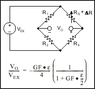
Therefore, if we replace R4 in Figure 3 with an active strain gauge, any changes in the strain gauge resistance will unbalance the bridge and produce a nonzero output voltage. If the nominal resistance of the strain gauge is designated as RG, then the strain-induced change in resistance, DR, can be expressed as DR = RG·GF·e. Assuming that R1 = R2 and R3 = RG, the bridge equation above can be rewritten to express VO/VEX as a function of strain (see Figure 4). Note the presence of the 1/(1+GF·e/2) term that indicates the nonlinearity of the quarter-bridge output with respect to strain.


Figure 4. Quarter-Bridge Circuit


Ideally, we would like the resistance of the strain gauge to change only in response to applied strain. However, strain gauge material, as well as the specimen material to which the gauge is applied, will also respond to changes in temperature. Strain gauge manufacturers attempt to minimize sensitivity to temperature by processing the gauge material to compensate for the thermal expansion of the specimen material for which the gauge is intended. While compensated gauges reduce the thermal sensitivity, they do not totally remove it.

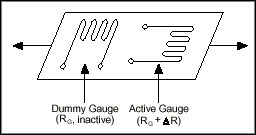
By using two strain gauges in the bridge, the effect of temperature can be further minimized. For example, Figure 5 illustrates a strain gauge configuration where one gauge is active (RG + DR), and a second gauge is placed transverse to the applied strain. Therefore, the strain has little effect on the second gauge, called the dummy gauge. However, any changes in temperature will affect both gauges in the same way. Because the temperature changes are identical in the two gauges, the ratio of their resistance does not change, the voltage VO does not change, and the effects of the temperature change are minimized.


Figure 5. Use of Dummy Gauge to Eliminate Temperature Effects


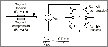
The sensitivity of the bridge to strain can be doubled by making both gauges active in a half-bridge configuration. For example, Figure 6 illustrates a bending beam application with one bridge mounted in tension (RG + DR) and the other mounted in compression (RG - DR). This half-bridge configuration, whose circuit diagram is also illustrated in Figure 6, yields an output voltage that is linear and approximately doubles the output of the quarter-bridge circuit.


Figure 6. Half-Bridge Circuit


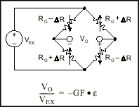
Finally, you can further increase the sensitivity of the circuit by making all four of the arms of the bridge active strain gauges in a full-bridge configuration. The full-bridge circuit is shown in Figure 7.


Figure 7. Full-Bridge Circuit


The equations given here for the Wheatstone bridge circuits assume an initially balanced bridge that generates zero output when no strain is applied. In practice however, resistance tolerances and strain induced by gauge application will generate some initial offset voltage. This initial offset voltage is typically handled in two ways. First, you can use a special offset-nulling, or balancing, circuit to adjust the resistance in the bridge to rebalance the bridge to zero output. Alternatively, you can measure the initial unstrained output of the circuit and compensate in software.

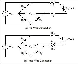
The equations given above for quarter, half, and full-bridge strain gauge configurations assume that the lead wire resistance is negligible. While ignoring the lead resistances may be beneficial to understanding the basics of strain gauge measurements, doing so in practice can be a major source of error. For example, consider the 2-wire connection of a strain gauge shown in Figure 8a. Suppose each lead wire connected to the strain gauge is 15 m long with lead resistance RL equal to 1 W. Therefore, the lead resistance adds 2 W of resistance to that arm of the bridge. Besides adding an offset error, the lead resistance also desensitizes the output of the bridge.

You can compensate for this error by measuring the lead resistance RL and accounting for it in the strain calculations. However, a more difficult problem arises from changes in the lead resistance due to temperature fluctuations. Given typical temperature coefficients for copper wire, a slight change in temperature can generate a measurement error of several me.
Using a 3-wire connection can eliminate the effects of variable lead wire resistance because the lead resistances affect adjacent legs of the bridge. As seen in Figure 8b, changes in lead wire resistance, RL2, do not change the ratio of the bridge legs R3 and RG. Therefore, any changes in resistance due to temperature cancel each other.


Figure 8. 2-Wire and 3-Wire Connections of Quarter-Bridge Circuit

Signal Conditioning for Strain Gauges

Strain gauge measurement involves sensing extremely small changes in resistance. Therefore, proper selection and use of the bridge, signal conditioning, wiring, and data acquisition components are required for reliable measurements. To ensure accurate strain measurements, it is important to consider the following:
  • Bridge completion
  • Excitation
  • Remote sensing
  • Amplification
  • Filtering
  • Offset
  • Shunt calibration


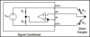
Bridge Completion – Unless you are using a full-bridge strain gauge sensor with four active gauges, you will need to complete the bridge with reference resistors. Therefore, strain gauge signal conditioners typically provide half-bridge completion networks consisting of high-precision reference resistors. Figure 9 shows the wiring of a half-bridge strain gauge circuit to a conditioner with completion resistors R1 and R2.


Figure 9. Connection of Half-Bridge Strain Gauge Circuit


Excitation – Strain gauge signal conditioners typically provide a constant voltage source to power the bridge. While there is no standard voltage level that is recognized industry wide, excitation voltage levels of around 3 and 10 V are common. While a higher excitation voltage generates a proportionately higher output voltage, the higher voltage can also cause larger errors because of self-heating.

Remote Sensing – If the strain gauge circuit is located a distance away from the signal conditioner and excitation source, a possible source of error is voltage drop caused by resistance in the wires connecting the excitation voltage to the bridge. Therefore, some signal conditioners include a feature called remote sensing to compensate for this error. Remote sense wires are connected to the point where the excitation voltage wires connect to the bridge circuit. The extra sense wires serve to regulate the excitation supply through negative feedback amplifiers to compensate for lead losses and deliver the needed voltage at the bridge.

Amplification – The output of strain gauges and bridges is relatively small. In practice, most strain gauge bridges and strain-based transducers will output less than 10 mV/V (10 mV of output per volt of excitation voltage). With 10 V excitation, the output signal will be 100 mV. Therefore, strain gauge signal conditioners usually include amplifiers to boost the signal level to increase measurement resolution and improve signal-to-noise ratios.

Filtering – Strain gauges are often located in electrically noisy environments. It is therefore essential to be able to eliminate noise that can couple to strain gauges. Lowpass filters, when used in conjunction with strain gauges, can remove high-frequency noise prevalent in most environmental settings.

Offset Nulling – When a bridge is installed, it is very unlikely that the bridge will output exactly zero volts when no strain is applied. Slight variations in resistance among the bridge arms and lead resistance will generate some nonzero initial offset voltage. Offset nulling can be performed by either hardware or software:
1. Software Compensation – With this method, you take an initial measurement before strain input is applied, and use this offset to compensate subsequent measurements. This method is simple, fast, and requires no manual adjustments. The disadvantage of the software compensation method is that the offset of the bridge is not removed. If the offset is large enough, it limits the amplifier gain you can apply to the output voltage, thus limiting the dynamic range of the measurement.

2. Offset-Nulling Circuit – The second balancing method uses an adjustable resistance, a potentiometer, to physically adjust the output of the bridge to zero. By varying the resistance of potentiometer, you can control the level of the bridge output and set the initial output to zero volts.

Shunt Calibration – The normal procedure to verify the output of a strain gauge measurement system relative to some predetermined mechanical input or strain is called shunt calibration. Shunt calibration involves simulating the input of strain by changing the resistance of an arm in the bridge by some known amount. This is accomplished by shunting, or connecting, a large resistor of known value across one arm of the bridge, creating a known DR. The output of the bridge can then be measured and compared to the expected voltage value. The results are used to correct span errors in the entire measurement path, or to simply verify general operation to gain confidence in the setup.